Lab 5 Part 2: Feedback Control (PID)
Overview
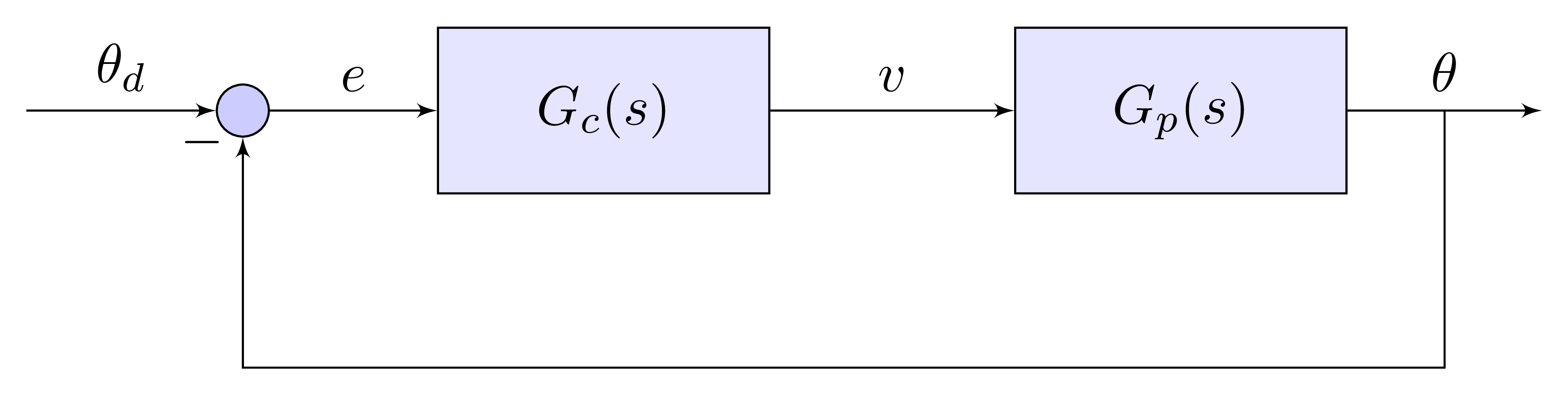
In this lab, you will learn to program your Arduino to perform feedback control of your DC motor. You will also investigate how the different control gains in a PID controller affect the step response. Finally, you will tune a PID controller to minimize settling time.
Pre-Lab Assignment
You cannot successfully complete this lab unless your system is setup so that a positive input to your motor control function results in positive change in your encoder output. Verify that on your open-loop pulse tests, positive commands lead to positive increases in the encoder output and negative commands lead to decreasing encoder output.
Proportional Control Testing Requirements
For the open-loop portion of this lab, you must do the following:
- program your Arduino to perform feedback control on your motor where the goal is to cause the motor to stop at the desired position as quickly as possible
- starting with proportional control, write Arduino code that requests
two inputs from the user, the proportional gain \(K_p\) and the
desired stopping point \(\theta_d\), and then runs a test for a
specified number of time steps
- your code must print real-time data to the serial monitor
- your code must stop printing after a specified number of time
steps
- constantly printing data to the serial monitor will cause problems and confusion
- use the
pyserialmodule to run tests and capture data using Python - write a Python function that takes \(K_p\) and \(\theta_d\) as inputs and then runs a test and plots the results
- your Python code must also be able to save data to
.csvfiles - run tests with multiple values of \(K_p\) and find values that lead to responses that are lightly damped, moderately damped, and over-damped
- investigate what happens with large values for \(K_p\)
PD Control
Once you have proportional control working, program your Arduino to do proportional + derivative control (PD control).
- modify your Arduino code to prompt the user for 3 things: \(K_p\), \(K_d\), and \(\theta_d\)
- write Python code that allows you to run PD tests quickly and easily, plotting the results afterward
- choose a \(K_p\) value that leads to a lightly damped response and then gradually increase \(K_d\) and observe how the response changes
PID Control
Once you have PD control working, implement PID and modify your Arduino code to request \(K_p\), \(K_i\), \(K_d\), and \(\theta_d\).
- starting with reasonable choices for \(K_p\) and \(K_d\), experiment with different values for \(K_i\) and see what you can learn
Final Tuning
Your final assignment for this lab is to find the “best” values for \(K_p\), \(K_i\), and \(K_d\). The “best” values are those that lead to the motor getting to the desired stopping position as quickly as possible with only a small amount of overshoot.
Feedback Control Report Specifications
You will turn in one report that covers both the open-loop and closed-loop portions of the lab. Here are the expectations for the feedback control (closed-loop) portion:
- Proportional control graph:
- overlay the responses for three different choices of \(K_p\) corresponding to lightly damped, moderately damped, and over damped
- PD graph:
- overlay the responses for three different choices of \(K_d\) while holding \(K_p\) constant
- PID graph:
- overlay the responses for several choices of \(K_i\) illustrating how \(K_i\) affects the step response
- Best Response:
- show the step response graph and settling time for your best gains
- include your chosen values for \(K_p\), \(K_i\), and \(K_d\)
- show the step response graph and settling time for your best gains
- Include your Arduino code for PID control and discuss how it works
- Answer this comprehension question:
- How does each term in a PID controller affect the system’s response:
- P:
- I:
- D:
- How does each term in a PID controller affect the system’s response: