IV. How does JPEG 2000 work?
|
1. Introduction 3. Comparison between JPEG and JPEG 2000 4. How does JPEG 2000 work? |
6. Conclusion 7. References |
At the core of the JPEG 2000 structure is a new wavelet based compression methodology that provides for a number of benefits over the Discrete Cosine Transformation (DCT) compression method, which was used in the JPEG format. The DCT compresses an image into 8x8 blocks and places them consecutively in the file. In this compression process, the blocks are compressed individually, without reference to the adjoining blocks4. This results in “blockiness” associated with compressed JPEG files. With high levels of compression, only the most important information is used to convey the essentials of the image. However, much of the subtlety that makes for a pleasing, continuous image is lost.
In contrast, wavelet compression converts the image into a series of wavelets that can be stored more efficiently than pixel blocks. Although wavelets also have rough edges, they are able to render pictures better by eliminating the “blockiness” that is a common feature of DCT compression. Not only does this make for smoother color toning and clearer edges where there are sharp changes of color, it also gives smaller file sizes than a JPEG image with the same level of compression.
This wavelet compression is accomplished through the use of the JPEG 2000 encoder1, which is pictured in Figure 4. This is similar to every other transform based coding scheme. The transform is first applied on the source image data. The transform coefficients are then quantized and entropy coded, before forming the output. The decoder is just the reverse of the encoder. Unlike other coding schemes, JPEG 2000 can be both lossy and lossless. This depends on the wavelet transform and the quantization applied.
The JPEG 2000 standard works on image tiles. The source image is partitioned into rectangular non-overlapping blocks in a process called tiling. These tiles are compressed independently as though they were entirely independent images1. All operations, including component mixing, wavelet transform, quantization, and entropy coding, are performed independently on each different tile. The nominal tile dimensions are powers of two, except for those on the boundaries of the image. Tiling is done to reduce memory requirements, and since each tile is reconstructed independently, they can be used to decode specific parts of the image, rather than the whole image. Each tile can be thought of as an array of integers in sign-magnitude representation. This array is then described in a number of bit planes. These bit planes are a sequence of binary arrays with one bit from each coefficient of the integer array. The first bit plane contains the most significant bit (MSB) of all the magnitudes. The second array contains the next MSB of all the magnitudes, continuing in the fashion until the final array, which consists of the least significant bits of all the magnitudes3.
Before the forward discrete wavelet transform, or DWT, is applied to each tile, all image tiles are DC level shifted by subtracting the same quantity, such as the component depth, from each sample1. DC level shifting involves moving the image tile to a desired bit plane, and is also used for region of interest coding, which is explained later. This process is pictured in Figure 5.
Figure 5 Tiling, DC Level Shifting, and DWT on Each Tile
Each tile component is then
decomposed using the DWT into a series of decomposition levels which each
contain a number of subbands. These
subbands contain coefficients that describe the horizontal and vertical
characteristics of the  original
tile component. All of the wavelet
transforms employing the JPEG 2000 compression method are fundamentally one-
dimensional in nature2. Applying one-dimensional transforms in the horizontal and
vertical directions forms two-dimensional transforms. This results in four smaller image blocks; one with low
resolution, one with high vertical resolution and low horizontal resolution,
one with low vertical resolution and high horizontal resolution, and one with
all high resolution. This process of
applying the one-dimensional filters in both directions is then repeated a
number of times on the low-resolution image block. This procedure is called dyadic decomposition and is pictured in
Figure 6. An example of dyadic decomposition1
into subbands with the whole image treated as one tile is shown in Figure 7.
original
tile component. All of the wavelet
transforms employing the JPEG 2000 compression method are fundamentally one-
dimensional in nature2. Applying one-dimensional transforms in the horizontal and
vertical directions forms two-dimensional transforms. This results in four smaller image blocks; one with low
resolution, one with high vertical resolution and low horizontal resolution,
one with low vertical resolution and high horizontal resolution, and one with
all high resolution. This process of
applying the one-dimensional filters in both directions is then repeated a
number of times on the low-resolution image block. This procedure is called dyadic decomposition and is pictured in
Figure 6. An example of dyadic decomposition1
into subbands with the whole image treated as one tile is shown in Figure 7.
Figure 7 Example of Dyadic Decomposition
To perform the forward DWT, a one-dimensional subband is decomposed into a set of low-pass samples and a set of high-pass samples. Low-pass samples represent a smaller low-resolution version of the original. The high-pass samples represent a smaller residual version of the original; this is needed for a perfect reconstruction of the original set from the low-pass set.
As mentioned earlier, both reversible integer-to-integer and nonreversible real-to-real wavelet transforms can be used. Since lossless compression requires that no data be lost due to rounding, a reversible wavelet transform that uses only rational filter coefficients is used for this type of compression. In contrast, lossy compression allows for some data to be lost in the compression process, and therefore nonreversible wavelet transforms with non-rational filter coefficients can be used. In order to handle filtering at signal boundaries, symmetric extension is used. Symmetric extension adds a mirror image of the signal to the outside of the boundaries so that large errors are not introduced at the boundaries. The default irreversible transform is implemented by means of the biorthogonal Daubechies 9-tap/7-tap filter. The Daubechies wavelet family is one of the most important and widely used wavelet families. The analysis filter coefficients1 for the Daubechies 9-tap/7-tap filter, which are used for the dyadic decomposition, are given in Table 2, and a graph of the corresponding wavelet is shown in Figure 8. The default reversible transform is implemented by means of the Le Gall 5-tap/3-tap filter, the coefficients1 of which are given in Table 3.
Table 2 Daubecies 9/7 Analysis Filter Coefficients
|
k |
Lowpass Filter (hk) |
Highpass Filter (gk) |
|
0 |
0.6029490182363579 |
1.115087052456994 |
|
|
0.2668641184428723 |
-0.5912717631142470 |
|
|
-0.07822326652898785 |
-0.05754352622849957 |
|
|
-0.01686411844287495 |
0.09127176311424948 |
|
|
0.02674875741080976 |
|
Table 3 Le Gall 5/3 Analysis Filter Coefficients
|
k |
Lowpass Filter (hk) |
Highpass Filter (gk) |
|
0 |
6/8 |
1 |
|
|
2/8 |
½ |
|
|
-1/8 |
|
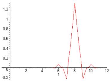
Figure 8 Wavelet corresponding to Daubechies 9-tap/7-tap filter
The standard supports both a convolution-based and a lifting-based filtering mode. For both modes to be implemented, the signal first needs to be extended periodically. This is done to ensure that for the filtering operations that take place at the boundaries of the signal, one signal sample exists and corresponds to each coefficient of the filter. Thus, how far the signal is extended on each side of the boundary depends on the number of filter coefficients. Convolution-based filtering is done by performing a series of dot products between the high-pass and low-pass filter coefficients and the extended one-dimensional signal. Lifting-based filtering is done by updating odd sample values with a weighted sum of even sample values, and updating even sample with a weighted sum of odd sample values1. For the lossless case the results are rounded to integer values. The lifting-based filtering for the 5/3 analysis filter is achieved by using (2) and (3) below:
![]() (2)
(2)
![]() (3)
(3)
where xext
is the extended input signal, y is the output signal and ![]() indicates the largest
integer not exceeding a.
indicates the largest
integer not exceeding a.
After transformation, all coefficients are quantized. This is the process by which the coefficients are reduced in precision. Dividing the magnitude of each coefficient by a quantization step size and rounding down accomplishes this. These step sizes can be chosen in a way to achieve a given level of quality. This operation is lossy, unless the coefficients are integers as produced by the reversible integer 5/3 wavelet, in which case the quantization step size is essentially set to 1.0. In this case, no quantization is done and all of the coefficients remain unchanged.
Following quantization, each subband is subjected to a packet partition3. Each packet contains a successively improved resolution level on one tile. This way, the image is divided into first a low quality approximation of the original, and sequentially improves until it reaches its maximum quality level. Finally, code-blocks are obtained by dividing each packet partition location into regular non-overlapping rectangles. These code-blocks are the fundamental entities used for the purpose of entropy coding.
Entropy coding is performed independently on each code-block. This coding is carried out as context-dependant binary arithmetic coding of bit planes. This arithmetic coding is done through a process of scanning each bit plane in a series of three coding passes. The decision as to which pass a given bit is coded in is made based on the significance of that bit’s location and the significance of the neighboring locations. A location is considered significant if a 1 has been coded for that location in the current or previous bit plane3.
The first pass in a new bit plane is called the significance propagation pass. A bit is coded in this pass if its location is not significant, but at least one of its eight-connected neighbors is significant. The second pass is the magnitude refinement pass. In this pass, all bits from locations that became significant in a previous bit plane are coded. The third and final pass is the clean-up pass, which takes care of any bits not coded in the first two passes3. After entropy coding, the image is ready to be stored as a compressed version of the original image.
One significant feature of JPEG 2000 is the possibility of defining regions of interest in an image5. These regions of interest are coded with better quality than the rest of the image. This is done by scaling up, or DC shifting, the coefficients so that the bits associated with the regions of interest are placed in higher bit-planes. During the embedded coding process, these bits are then placed in the bit-stream before the part of the image that is not of interest. This way, the region of interest will be decoded before the rest of the image. Regardless of the scaling, a full decoding of the bit-stream results in a reconstruction of the whole image with the highest possible resolution. However, if the bit-stream is truncated, or the encoding process is terminated before the whole image is fully encoded, the region of interest will have a higher fidelity than the rest of the image.